
What is DFM?
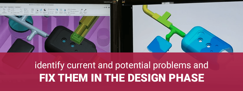
Design for manufacturability (also called design for manufacturing or DFM) is the process of designing products in a way that will result in the best manufacturing outcomes. DFM enables original equipment manufacturers and contract manufacturers to identify current and potential problems and fix them in the design phase, which is the least expensive time to address them. DFM can influence all types of project decisions, including but not limited to:
- Type and form of raw material used
- Dimensional tolerances
- Wall thickness and draft
- Secondary processing, such as finishing
- Overall method of manufacturing the product
What is DFM in plastic injection molding?
Design for manufacturability can be done in any type of manufacturing, but in plastic injection molding, there are specific problems that it is used to solve. Defects that occur in plastic injection molding can be caused by flaws in part design, mold design, material temperature, injection pressure, cooling time, and other parts of the manufacturing process. Nearly all of these types of defects can be predicted and avoided through design for manufacturability.
Who does DFM?
OEMs that engage a CM to do design for manufacturability can expect the engineers at the CM to lead the DFM process, carrying out the analysis, detecting problems, and formulating solutions. Engineers carrying out DFM in plastic injection molding must have extensive experience in custom plastic injection molding and injection mold tool building.
However in any given project, both engineers and product designers at both the original equipment manufacturer and the contract manufacturer are involved in the DFM process. Engineers and product designers at the OEM are responsible for providing the CM with all plans, materials, and specifications related to the component, and as much information as possible about the product itself and its uses. As the DFM process progresses, and often through manufacturing itself, communication among all parties is a good predictor of success.

What does the DFM process look like in plastic injection molding?
DFM can take place in the early concept phase, in the design phase, or at any phase in the entire product life cycle. Regardless of the timing, DFM in plastic injection molding includes the following phases and activities:
Analysis of Plans and Identification of Concerns
The OEM provides the CM with all existing plans, documentation, and information regarding the project, including as many details as possible about not just the component but the overall product and its uses. The OEM describes to the CM any concerns they may have about the manufacturability of the component or problems they might anticipate in its manufacture. The CM engineers consider these concerns and review all plans and documentation to identify potential issues that could affect manufacturability.
DFM Simulation
The CM engineers use specialized mold flow simulation software, such as Sigmasoft, to simulate the injection molding processes. They use the software to create real 3D simulation of flow, heat flux and warpage for injection molding, including the complete mold with all details. During the simulation, they inspect the project for all of the parameters in the checklist for DFM in plastic injection molding, identifying any problems that will occur unless changes are made to the design, mold, materials, etc.
Presentation of Results and Recommendations
Upon conclusion of the simulation, the CM engineers prepare and share the results of the simulation with the OEM and recommend the best solutions to the problems identified. A key deliverable to the OEM from the CM is a document communicating the results of the DFM process and the resulting recommendations, including screen shots from the simulation process. The document includes:
- Conditions used for the simulation:
- Material
- Shot Size
- Material Temperature
- Mold Temperature
- Fill Time
- Pack Time
- Total Mold Closed Time
- Gate Size
- Nozzle Size
- Gate Freeze
- Pack Pressure
- Press setup information, including:
- Material data sheet with specifications sourced from the material supplier, e.g., ExxonMobil. (DFM should include guidance from the CM on resin raw material and other raw materials selection to meet the project’s plastic component requirements.)
- A section covering each parameter that was tested in the simulation, presenting simulation results. A full list of parameters can be found in the checklist for DFM in plastic injection molding below.
- Multiple sections comparing the results of different variables introduced in the simulation and the results achieved, for example, comparison of various packing pressures and the resulting sink marks, hot spots, and voids
- A summary of concerns that arose from the simulation
- A summary of the recommendations and remedies that the contract manufacturer recommends to complete the design for manufacturability process.
Prototyping, Testing, and Completion
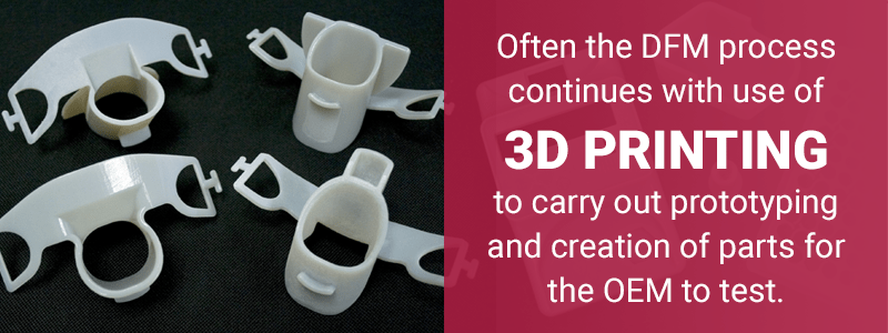
Often the DFM process continues with use of 3D printing (additive manufacturing) to carry out prototyping and creation of parts for the OEM to test. As needed, portions of the DFM simulation described above can be repeated, along with prototyping and testing, until the product is ready for manufacture.
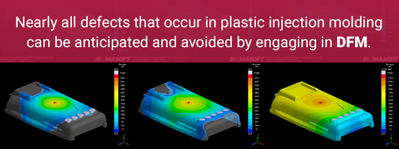
Defects that occur in plastic injection molding can be caused by flaws in part design, mold design, material temperature, injection pressure and cooling time — nearly all of which can be anticipated and avoided by engaging in DFM.
Key Problems In Plastic Injection Molding
The most common plastic injection molding problems include:
Flash
A thin layer of plastic that flows outside of the cavity, typically where the two halves of the injection mold meet, creating a flap or excess material that must be trimmed. Flash decreases product quality, can add time to the manufacturing process, and damage your injection mold so avoiding plastic injection molding flash is necessary.
Weld Lines
A line, notch or color change on the molded part caused by the convergence of two separate flows of molten plastic, which can reduce aesthetics and/or strength. Creation of weld lines are unavoidable, but there are some considerations and ways to fix injection molding weld lines.
Sink Marks
A local depression on the surface of a part, typically caused by a part thickness that is too large for the resin type. Learn some common techniques for resolving sink marks for injection molded parts.
Short Shots
An incomplete part where the molten plastic does not fill the entire mold cavity, resulting in a portion where there is no plastic, e.g., a missing prong on a plastic fork. There are several causes for short shots and to remedy them depends on the causes for each individual case.
Burn Marks
Discolorations on the part surface that are often a dark black or red color, where plastic material overheated and burned against the injection mold.
Brittleness
Insufficient strength in the part, leading it to crack or break easily — has a variety of causes and remedies.
Delamination
Visible surface layers on the finished product that can be peeled — has a variety of causes and remedies.
Jetting
A deformation in the finished piece that can affect strength and aesthetics, occurring when some of the molten plastic material sprays into the mold cavity before the normal flow.
Sinks
Depressions in the surface of the piece, occurring when the mold is not properly filled or when excessive part thickness causes too much part shrinkage in a localized area.
Voids
Air gaps or pockets beneath the surface of the finished part, which can threaten the strength and structural integrity of the part and cause it to fail.
Splay
A cosmetic defect where moisture in the material creates streaks on the surface of the part.
Bubbles/blisters
Bubbles or blisters form when air cannot escape the mold cavity as the material is injected, which can affect strength and aesthetics.
Warping
Surfaces or walls on the part twist or bend as the part cools — has a variety of causes and remedies.
Flow lines
Visible streaks or waves in the surface of the part, caused by inconsistent cooling of the material.
Design for manufacturability greatly reduces or eliminates the most common defects that can occur with plastic injection molding. The case study below is just one example of how DFM was used to solve a set of problems in the plastic injection molding process.
Case Study: Solving Quality Issues for a Medical Device
When the OEM of a medical device was experiencing quality problems in the manufacturing phase, they turned to plastic injection molding CM Crescent Industries for a solution. The CM used design for manufacturing to eliminate these problems and create a value-added, problem-free manufacturing process.
Crescent Industries started by learning about the product, a device used to help heal broken bones through ultrasound, and discussing it with the OEM’s engineers. The OEM had been experiencing jetting of the substrate material in the clear window, and the parts were failing inspection because the windows were not clear. Based on the information gathered, the CM determined that the OEM’s current injection molding process was the root cause of the quality issues. It was likely that substrate material had been re-melting and mingling with the clear resin of the window as it was filling. The co-injection of three different materials was the manufacturing process that was causing the parts to fail.
Design revisions were needed to improve the process, but the OEM had only legacy data for the device. Rather than relying solely on 2D drawings and 3D solid models, Crescent Industries employed 3D printing to create prototypes demonstrating their recommended design modifications. The OEM was able to use the redesigned and 3D printed parts in their completed product assembly as if they were assembling and testing a unit that had gone through the entire manufacturing process. This approach not only shortened the time needed for redesign, but assured the OEM that they would be receiving a finished medical device that met their needs.
In all, the new approach for manufacturing the device included:
- Revising the product design
- Designing and building new tooling
- Implementing ultrasonic welding and product printing
- Other value-added manufacturing steps
Finding the Right Contract Manufacturer
Not all contract manufacturers are equipped to prepare your project for success using DFM. When looking for a plastic injection molding contract manufacturer, make sure to:
- Ask their sales team if they provide design for manufacturability as a service
- Consult their website for a description of their DFM services along with any DFM case studies of their past work
- Request to see the list of items they evaluate in their DFM process and compare it to the recommended checklist for DFM in plastic injection molding
- Establish that they employ engineers with extensive experience in custom plastic injection molding and injection mold tool building
- Set up a consultation with an engineer from their DFM team to discuss how they would handle your project
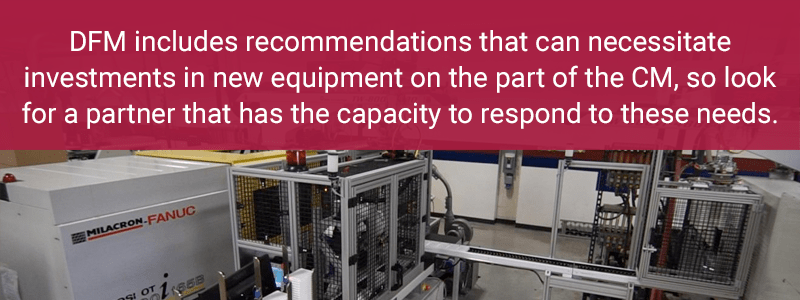
DFM includes recommendations that can necessitate investments in new equipment on the part of the CM, so look for a partner that has the capacity — the facilities and cash position — to respond to these needs.
A Successful Project Handoff
A successful plastic injection molding process starts with a successful handoff between the original equipment manufacturer and the contract manufacturer. When initiating a project, in addition to providing your CM with your CAD models, 3D models, other planning documents, as well as any existing prototypes or samples of previously manufactured iterations, expect to have at least one if not more DFM consultations with them. In these conversations, you’ll be sharing as many details as possible about the overall functioning of the product, beyond the part they’re manufacturing.
Understanding that some constraints may apply to sharing information about projects regulated by International Traffic in Arms Regulations and other policies, with a signed CDA and NDA in place, the more information your CM can have about the overall product’s use and functioning, the more they can do to make recommendations that result in the best possible design and manufacturing for your component. The best results from the DFM process come when the CM knows as much as the OEM’s engineers do about the end use of the product and all the different components that it interfaces with.
Design for manufacturability brings the results of in-depth examination of product design to bear in creating the best possible manufacturing outcome in plastic injection molding. By seeking out and engaging with a contract manufacturer skilled at DFM, original equipment manufacturers can produce plastic injection molded parts with confidence, knowing that the process will run smoothly and the resulting components will meet their needs.
